Summer 2024, I worked for a Boston-based startup named De-Ice. As their name suggests they were trying to develop novel aircraft anti-icing technology, seeking to replace the time-consuming and environmentally damaging method of chemical glycol sprays with an inductive heating method. If you don’t know what inductive heating is, here’s a super easy-to-digest 101:
To accomplish this inductive heating effect, De-Ice developed their own inverter to convert aircraft main power supply DC to ultra-high-frequency AC which is subsequently run through a set of thin tape-like strips hugging the surface of an aircraft and particularly its wings. Inverters (and their inverse relative the rectifier which converts AC to DC) can get big. To get an idea of this take a look at your laptop charger chord, you might notice an awkwardly big box somewhere along the line. That’s most likely your laptop’s rectifier! It’s amazing that despite laptops themselves becoming lighter than air and yet more powerful, we still haven’t really found a way to make this cumbersome rectifier go away. Welcome to the world of power electronics!
Anyway, I digress. Ironically, despite De-Ice’s primary goal being to heat things up, I spent most of my summer trying to cool things down! You can imagine that when dealing with enough energy to melt ice off of an entire aircraft, the inverter gets pretty damn hot. Overheating inverters pose a safety risk… in that the inductors and capacitors on those things will explode. Now, I don’t know the FAA guidelines for aircraft safety, but something tells me that aircrafts and explosions don’t go well together.
Thus, I present Wendy! Wendy is a test bench designed to control and monitor inverter cooling. She is named Wendy after the lead vocalist from Red Velvet, and her name is a play on the word “windy”, since as you can probably guess, the inverters were fan-cooled.


Overview:
The design goal of Wendy is to design a system that offers transparency to the thermals of the inverter board while mimicking actual operation. When actually mounted and operational inside an aircraft, multiple inverter boards are placed together on a rack inside an aluminum box with fans drawing air through the box to cool the components. The issue with this is that when inside the aluminum box, there is no information regarding component temperature and how they respond to a change in fan speed, a change in inverter input power, or a change in load resistance. However, this transparency is necessary both as a safety precaution and to educate future designs of the inverter. Prior to Wendy, De-Ice used resistive thermal devices (RTDs) that were permanently epoxied to critical components on the inverter board, inserted this board into the aluminum box along with its neighbors, and routed out a massive braid of RTD cables to take around 10 point-reading temperatures. This method is tedious, non-comprehensive, and destructive to the inverter board that is being tested. However, the temperature data collected by this board was used as the reference for the temperatures expected through Wendy’s readings. If Wendy could read temperatures (via infrared camera) that accurately reflect the temperatures read from the inverter board with RTDs attached to it while also being much easier to use and non-destructive to the board under test, Wendy would be a success.
Initial Concept & the Obvious out of the way:
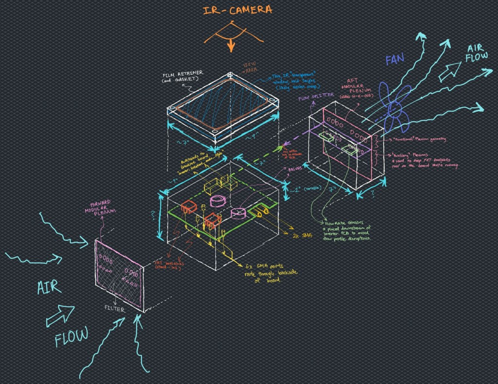
Above was the initial v1 sketch concept for Wendy. No need to explain it as it serves just as a cool visual. To get the obvious out of the way, the most important three requirements for Wendy were
- the inverter remain operational
- the air speed/temperature over the inverter stays roughly the same to achieve the same rate of convective cooling.
- the temperatures are readable by an infrared camera
Accomplishing point 1 is just a matter of clever and careful design, keeping connector ports and critical outputs points open. Accomplishing point 2 is more difficult, but also simply comes down to keeping the flow channel geometry over the inverter consistent with in-situ (shorthand for “operational conditions”) and simply adjusting the fan speed to achieve a mimicked flow rate. Point 3 was what worried me the most at first. How do I get the infrared camera to SEE the inverter? I can’t just keep the top side of the inverter board open… this would make a normally fully-enclosed object suddenly open and completely disrupt the airflow/cooling. I also cannot just use glass or clear acrylic as an enclosure. Just because something is visually transparent does not mean it’s infrared transparent! As I started browsing online, I began finding some state-of-the-art germanium infrared slabs and lenses (apparently Germanium is infrared transparent up to 95%), but these things cost hundreds, if not thousands of dollars for a tiny slab that didn’t even suffice as a window for the entire inverter. As a thrifty startup, there HAD to be a better, more reasonable option.
The GLAD moment
One day towards the end of the 2nd week of this internship, I was eating lunch with the team. It was a simple deli sandwich from the Market Basket next door (a Boston staple) wrapped in your generic food wrap. It hit me that there are actually 2 variables that determine how electromagnetically transparent a material is. Material and thickness!

Where


We see as x approaches 0, the fraction of transmitted light approaches 1 (as expected). Hence, maybeeee we could develop a thin window-like film that keeps the inverter board visible to the infrared camera yet keeps the board enclosed.
Thus, right after lunch, I bounced straight back to the Market Basket and bought 3 different rolls of food wrap for around $5 and submitted my first work-related R&D expense. The rest is history.
Food wrap works, but has its own problems
As excited as I was for the idea of using food wrap as an infrared window, this solution presented its own problems. For one, food wrap is not rigid, and when a fan is blowing air through a box at around 4 m/s, Bernoulli’s Effect causes the food wrap to bow inward, and if in contact with the hot components on the inverter, the wrap could melt. At first, I tried a simple retaining ring design that pulled the food wrap extremely taught around the frame, but even then, the middle of the food wrap window would bow inward enough to worry me. Thus, I added the x-shaped support on the frame, adding 5 evenly spaced support points on the food wrap to prevent it from bowing inward.
The second issue with food wrap, or really any kind of barrier, was that despite it being “highly infrared transparent”, it is not “100% infrared transparent”. This means that all temperatures read through the food wrap should not be trusted without an adjustment factor. Thus, I made a calibration routine where I measured components of known temperature with and without the food wrap as a film in-between. I even adjusted the distance between the component under measurement and the film to see if that made an impact (only very slightly, not enough to be meaningful). This was done across about 10 sample temperatures from 0-120 C which is the max allowable temperature the inverter is allowed to reach. A nice linear relationship was characterized and a single adjustment factor was obtained.
Radiated heat loss, is it Important?
Another huge question I had to ask myself was whether radiation heat transfer was a negligible factor. In-situ, the inverter boards would be enclosed by either aluminum or by the backside of another inverter board of comparable temperature. With Wendy, the inverter board is enclosed by a practically transparent film of food wrap, which would sink much more heat radiatively. The sketch below illustrates this concern, as well as an initial proposed solution for fixing it in case it was necessary.
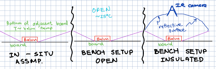
I will spare us the details of the analysis, but it turns out radiation effects only account for only about 4-7% of the total heat transfer of hot components, hence it was deemed unnecessary and not worth the effort of creating a mitigation.
Upstream Heat Sinks… a Lingering Mystery
Another question that I unfortunately left De-Ice without answering was whether or not it is important to replicate some of the upstream heat-generating components that are not inherent to the board-under-test and hence are not going to be modeled heat sources on Wendy. This came in the form of a set of 2 heat sinks that sit right at the air inlet of the aluminum box. These 2 heat sinks are the ONLY component on the backside of the inverter board and they are designed to carry heat away from the family of Gallium-Nitride (GaN) switching transistors which otherwise would be far and away the hottest components on the inverter without the heat sinks.
In order to accomplish this I tried to perform both hand calculations and even tried my hand at some COMSOL multiphysics thermofluid simulations, but neither gave me any results I was willing to trust. Also, the implications of having to implement an artificial heat source on Wendy to resistively heat a pair of dummy upstream heat sinks is simply too complex of a design addition to be worth adding. Hence, the rabbit hole was dropped despite how curious I was of its affects.
“Energy doesn’t flow in wires”
Finally, I bring up one of the most unique problems I have ever encountered in my engineering career to date: electromagnetic interference. Yes, this is one of those things you’re probably taught about in school or learn about in physics or in passing, but it’s not a problem you actually run into often unless you are a signals engineer (a super niche field). Even at SpaceX, I was always looking at avionics that included some kind of “radiation shield”, which I just took for what it was and didn’t ask many follow up questions.
While building Wendy, however, I finally came face-to-face with this beast. Thanks to the high power and switching frequency of the inverter, that thing was an electromagnetic minigun, spewing enough noise to disrupt basically any unencoded signal in its vicinity, wired and wireless. Thankfully, because bluetooth and i2c signals are engineered well, I was still able to listen to Red Velvet and the signal line between my air flow sensor and my central Arduino still worked like a charm. The problems arose in the fan tachyometer and the digital read out for the airspeed. It took me hours of head scratching to figure out why my fan was not responding as expected to the input PWM signal, and why my airspeed digital read out would display gibberish after the power to the inverter was ramped up past around 50%. The solution at the end of the day? To quote Leo my coworker “When in doubt, choke it”.
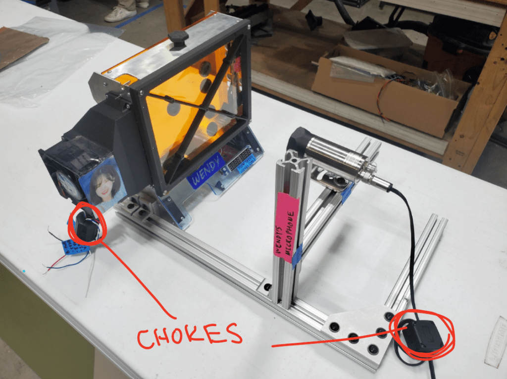
I’ve forgotten why a choke works (in theory), but it does, I was happy, and Wendy was back to her normal self.
Addendum: Altitude Effects
The last thing I want to mention I worked on at De-Ice is a campaign to calculate the difference in temperature of the inverter board at a different altitude, namely the average cruising altitude of a passenger aircraft. At that height, the density and viscosity of air changes! Yes, the air is far cooler too, but this is actually a non-factor because the air used to cool the inverter will still originate from the cargo hold of the aircraft which is regulated at close to room temperature.
This change in density is quite puzzling because it causes 2 changes that actually work against each other.
- The rate of convective heat transfer between the electronics and the air reduces since there is physically less air to pick up the heat. This would cause the inverter to be hotter.
- The air volume flow rate of the fan (at the same electrical power) increases since there is less mass to move. This would cause the inverter to be cooler.
I really enjoyed solving this problem, and once again I will not bore you with the equations other than lazily slapping my whiteboarding picture here. At the end of the day, it turns out that all else held constant, the inverter will be worst-case 10% hotter at altitude.

Extra
An extra picture of Wendy in action and not just on display! I unfortunately cannot show any images containing the inverter board or any results/thermal images.

