Engineering Analysis Using the Finite-Element Method
ME C180 was an introductory course to the finite element method taught by Professor Sanjay Govindjee, a Structures and Materials Professor in the civil engineering department. The finite element method is a mathematical method designed to help engineers break down complex physical problems and model/simulate them in a virtual environment. The essence of the method lies in the name. A body is broken up into geometric “elements” each with a set of nodes (an example would be breaking up a simple L bracket into 100 different cubic elements with a node at each corner). For each element, the governing set of physical differential equations is solved for across the nodes (this set of differential equations is problem-specific). However, since a perfect solution across each element rarely exists, the problem becomes a minimization of error problem. Since minimization problems have an infinitely large potential solution space, a test function from a “finite” subset of potential solutions (for example a 2nd degree polynomial) is used to minimize over. Hence, “finite-element”.


I’ll preface this blog post by saying this is perhaps the most difficult class I have taken at Berkeley up until now. This difficulty was not only the classic “unbeatable curve in a basic class” difficulty. This class was fundamentally difficult. The lectures were humbling. The students (a quarter of them graduates) were all brilliant and there by choice, as is true for most electives. The finite element method was created by humans for the sake of approximating complex problems. As a result much of the math was quite hand-wavy. Most of my engineering classes rely on hard physical equations that are massaged to desired forms using hard math. This class uses the hard physical equations as an end goal, but does whatever the hell it wants mathematically to achieve said goal. “Let’s approximate an integral of f(x) from -1 to 1 as 2 * f(0)”. “Let’s rewrite this 3 x 3 tensor as a 6 x 1 vector by taking advantage of symmetry”. “Let’s put together a 5 x 5 matrix using five 2 x 2 matrices”. I would check out some lectures based on sheer information overload.
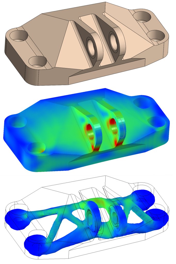
Without further to do, here’s my run through of the curriculum. The first third of the class sought to introduce us to the basics of how a finite element model is set up. We covered strong form equations (typically the physical law) and how the weak and minimization forms were derived from the strong. We also covered test and trial functions, both of which were necessary for the derivation of the weak form and are also where the finite solution spaces come into play. To wrap up the basics, we covered the Dirichlet (essential) and Neumann (natural) boundary conditions as well as the location matrix (the key to going from element-by-element solutions to a full-body solution). With that, any finite element problem is fully defined. The second third of the class was a round-robin style coverage of all the different types of problems that the methods we learned in the first third could be applied to: static stress analysis, fluid dynamics, heat transfer, oscillatory modes, the list goes on. The last third of the class focused on optimization and using the FEM to do more than just analysis but also to help in the design process. Imagine simply defining loads on a block of material, defining a maximum material quantity, and watching the computer cut away at the block until the optimal design has been reached. Behold, topology optimization, powered by FEA.
Professor Govindjee was a great professor with a clear lecture style and a patience for questions. He also balanced the curriculum in the class well, focusing heavily on theory in lecture, yet assigning an abundance of practical labs and homework assignments that used many common industry finite elements tools such as ANSYS (the user-friendly one), and FEniCS (the advanced, open-source python library). These assignments gave us all something physical to connect abstract lecture concepts to and also gave us practice with setting up boundary conditions, choosing element types, mesh densities, and other very real skills.
Despite its difficulty and the hit my GPA took, I have no regrets about my decision to take this class. FEA is a cornerstone skill that any mechanical engineer must have. Without it, designs remain fancy pieces of art. Without it, testing must be done physically, which wastes time and materials (albeit FEA is no replacement to physical testing but can certainly reduce the amount necessary). Without it, an entire research field of computational mechanics never comes to be.
Food for Thought
Below is an 8-node square element, the most common type of element used for its balancing of runtime and accuracy. Each node on the element must be associated with a “shape function” that holds the Kronecker property: the function must evaluate to 1 at the node it is associated with and 0 at all other nodes. What is the shape function of the highlighted node?
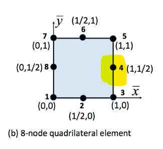
Bonus: this type of element provides an nth order polynomial approximation. What is n?
