
Overview:
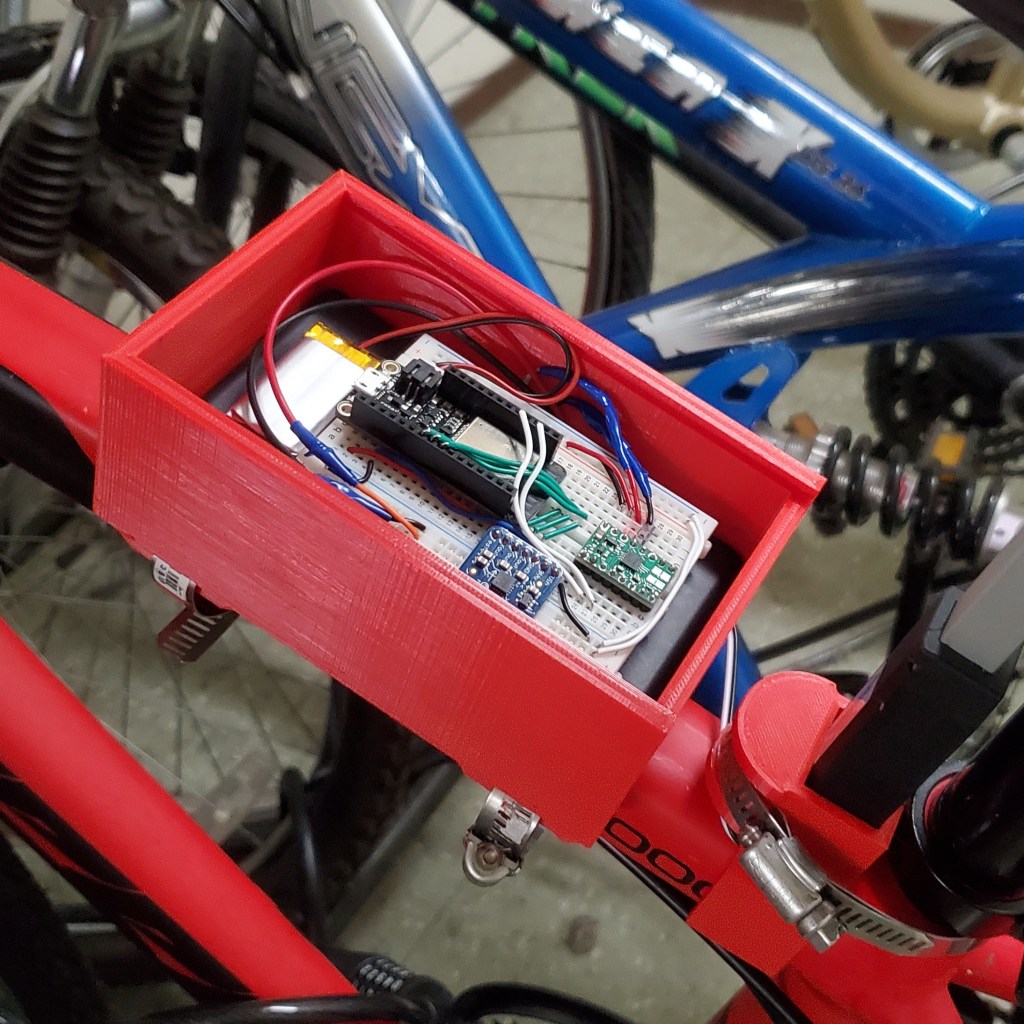
To combat the army of bike thieves in Berkeley, we fight wrenches and cable cutters with… borderline harassment! Please check out the YouTube video linked to get a full breakdown of what we made. Even if you don’t care about the technical aspects of the work, I highly encourage you to at least watch the first 1:30, which is a short skit put together by my partner and I. Also, shown above are images of the system in its entirety fully installed on my bike (with the exception of the missing lid to allow visibility for the circuitry).. For the rest of this post, I will be documenting the technical aspects of our work. All, IoT devices need Sensing, Computation, and Actuation. Reliable mechanical design for withstanding the elements and phone message notification were neat added touches to round out the practicality of this project.
Sensing:
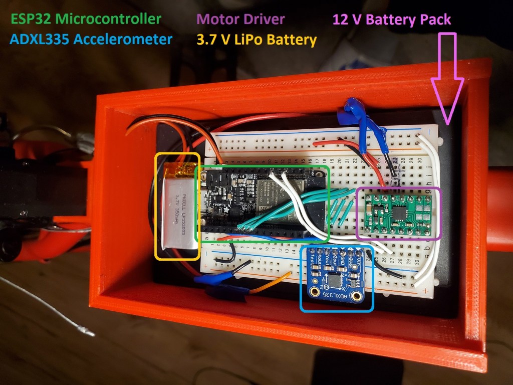
For Sensing, we used an Adafruit ADXL335 triple-axis accelerometer wired up the the ESP32 Micropython controller. Shown in the following set of plots are the results of a unit test on the ADXL335. You can see fluctuations in the isolated X, Y, and Z tests for the first 10 seconds followed by random motion on the last 10.

Computing:
Computation was done solely within the main.py function of the ESP32 and powered by a 3.7 V rechargeable LiPo battery. Classifying what is considered a bike being stolen vs what is considered just a strong gust of wind or student bumping into the rack was the primary problem to solve. Our solution was simply to set two parameters. The THRESHOLD parameter is the calibrated acceleration reading used to determine when a bike is being jostled “strong enough”. The DURATION parameter (set at 5 seconds) is the time window which we sense for successive signals that exceed the THRESHOLD. In practice, following occurs:
- When the system is turned on, it uses the first 1 second to calibrate what it considers a “still” bike. These “still” acceleration values are stored and used as a benchmark to compare future readings to.
- Once the short calibration period is over, the red LED on the ESP32 will turn on indicating the system is in sensing mode.
- IF the bike senses acceleration above THRESHOLD, it will set off a stopwatch.
- IF the bike senses another acceleration value above THRESHOLD, it will stop the stopwatch.
- IF the time elapsed < DURATION, actuate! ELSE, return to step 3.
The philosophy behind this is as follows: The system will reject non-critical disturbances that occur over long periods. These disturbances are the aforementioned gusts of wind or student bumping into the bike. However, critical disturbances associated with a bike being stolen are often either continuous or at the very least occur over much shorter periods. These disturbances may be repeated jostling to break the bike lock or shocks from successive bumps in the road. So long as these critical disturbances happen within 5 seconds of each other, the system classifies them as suspiciously close together and will begin the shafting process.
Actuation:
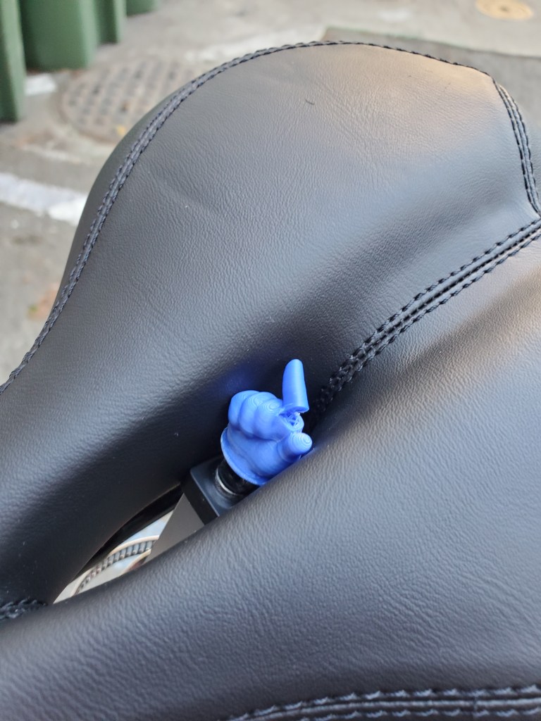
This is the project’s punch line. The actuation component of this IoT device is a 7-lb thrust force linear actuator that directly probes the thief’s ass (for lack of a better word). The control of this actuator is simply an alternating square signal for extending and retracting the shaft. This control is facilitated by a DRV8833 Motor Driver and powered by a 12 V battery pack.
Mechanical Design:
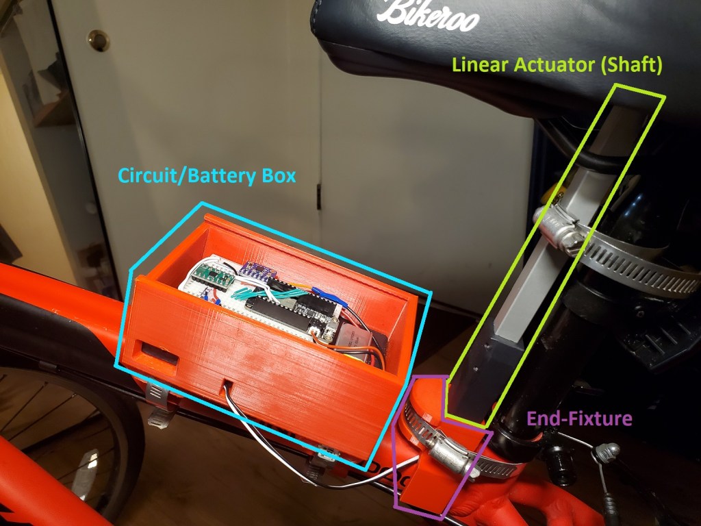
For mechanical design, we needed an inconspicuous way to house the electronics (board + battery packs) and a reliable way to mount the linear actuator. We used SolidWorks to CAD a couple components and 3-D printed them in specifically chosen colors of PETG that match the bike color. PETG was chosen for its relative strength among standard 3-D printer filament as well as its tendency to remain stiff under heat (relative to other plastics).
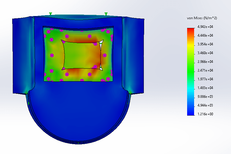
For the base of the Linear Actuator, we designed an end fixture component that would not slip with 7 pounds of normal force. Design requirements included rotational constraint and ability to withstand cyclic loads of 7 pounds. Here were a couple simple FEA studies I did with this component. The max Von Mises Stress is well within the range of the yield stress of PETG.


Notification Via Internet:
The last component of the project was the notification system. My project partner took most of the work here and used any detectable Wifi networks or the bike user’s hotspot to send an email notification via IFTTT to the user. For more information on how IFTTT works, you can visit their website https://ifttt.com/.