During my summer 2020 internship, I was fortunate to have an opportunity to work with Hermes Robotics, a bay-area based startup that focuses on retro-fitting technology into trucks to enable them to drive autonomously. Prior to the start of my internship, our CEO and CTO had both already designed and implemented the crucial systems such as the mechanical actuators for the gas pedal, brake pedal, and steering column. As well, they used Velodyne lidar equipment to virtually map out the vehicle’s environment, essentially acting as the vehicle’s “seeing eye”. Until this point, the retro-fitted vehicles were at level 2 autonomy (see levels of automation). This meant that the vehicle must always have a passenger in the drivers seat ready to take over the vehicle at any moment’s notice. Due to this, the passenger could manually control certain aspects of the vehicle if necessary, including the shift stick. However, to reach a slightly higher level of autonomy, processes such as gear shifting needed to be automated. My task was to help design a servo-powered mechanical system to control the gearstick of a 2016 RAM 1500 (shift by cable system).
System Requirements:
If you have ever driven a car with a mechanical gearstick, it is clear that the motion of such gearsticks are quite complex. Unlike a steering wheel (which is purely rotational motion about an axis) or the gas pedal (which is purely rotational about a pivot), the gearstick almost seems to exhibit random motion. In order to get from “park” down to “drive”, the driver must pull the gearstick handle up and towards them, effectively unlocking the lever, before pulling down and letting the stick spring back into the locked state. Additionally, the process of pulling down is by no means smooth. There are divots that mark the position of other gears such as “neutral” or “reverse and require more force to overcome. To accurately understand the way a gearstick works, I pulled the plastic cover off from under the steering wheel and tried observing what happens mechanically as I pull the lever. In the video below, I did my best to document the behind-the-scenes process of a typical gearstick.


There are 3 main components of the shifting system. The first is the bracket. The metal shift bracket is the most clearly visible components and is the one which rotates as a whole as the lever is pulled. The second is the bracket base. The bracket base is the metal piece which does NOT move as the lever is pulled and acts as a mount for the bracket itself. The bracket base and the bracket are connected by a compound joint which allows for the bracket to rotate in along two different axes. The first axis runs perpendicular to the bracket base and accommodates the main pulling motion of the lever. The second axis runs in a vertical orientation and accommodates the locking and unlocking of the lever. The third and final component is the most important. At the very back of the bracket, in the shadows, there is a little ball-and socket knob that connects to a long white piece. This long piece houses the cable which directly connects to the transmission of the car! The pulling or pushing of this cable does *something* within the gearbox which shifts the vehicle’s gear. The actual process is unimportant to me so I have blackboxed it. Controlling which gear to shift to is more directly controlled by the extent to which the cable is pulled.
With all this in mind, my mechanical system must meet the following 3 basic requirements:
- Actuate the bracket in two different degrees of rotational freedom .
- Produce enough torque to overcome the resistive forces of the bracket’s friction to the bracket base and the pulling force of the cable.
- Incorporate either an electrical feedback system or a mechanical system that is able to act as a backup to the servos, preventing them from over or undershooting from the target gear.
Abandoned Ideas:
This build presented 3 unique challenges:
- Though it was not strictly required, our CEO suggested that the system I design must be able to still allow the person in the driver’s seat to override the servos quickly and take control of the stick in the case of an emergency.
- This build does not start on a blank canvas. I needed to work around the existing structures of the vehicle. There is only so much room in the driver’s seat for new systems while still allowing a person to sit in the seat.
- I needed to try to minimize the number of servo actuators I used. The basic rule of thumb is that the more actuators present, the more room there is for error.
The first design idea was the most straightforward. I simply needed to remove the complex structures such as the bracket and the bracket base. With only the cable remaining, all I needed to do was find a suitable location to fit a single servo motor attached to a pulley. The pulley would either reel the cable in or release, causing a change in gears. The conflict is with both challenge 1 and 2. With this system installed, there would no longer be a physical shift lever, rendering the passenger helpless if he/she needed override the system. Additionally, the amount of torque required to reel in the cable is too high for a traditional servo motor. Thus, a reducer would be required. Reducers are both bulky, heavy, and may be expensive depending on the quality and the ratio. Essentially, all the reducer does is sacrifice rotational speed for higher torque. There is little room for such a bulky and heavy piece of equipment (not to mention the motor itself) far back to where the cable begins.
The second design idea was to use a single motor/reducer combination to rotate the bracket along the primary axis. The challenge here lies within how to effectively get the bracket to the “unlocked” prior to motor actuation and back to the “locked” state after the motor has found the correct angular location of the next gear. The solution was to use a custom manufactured “terrained” piece shown below. The concept is for the hills of this terrained piece to facilitate the locking/unlocking motion in the second degree of rotation without needing another actuator. The terrained piece would act as a rail while the tip of the bracket would accommodate a wheel that would roll over the hills. The spacing on this terrained piece reflect the spacing between differing gear states. This design would overcome challenges 1 and 3, allowing for the driver to still operate a the stick and requiring only a single actuator. However, after much design iteration and FEA on my part, I deemed the idea dead. The magnitude of the displacement between the locked and unlocked states of the bracket were just too great while the rotational displacement between gear states were too small. The slopes of the hills on the terrained piece were too steep. The motor would not be able to push a wheel over the top of the hill with only horizontal force.
The third idea was the most creative, and the one I explored the least. The idea is to use a nautilus gear. Since the automation required two degrees of motion, but I wanted to try only using one actuator, the nautilus gear was a potential solution to achieving both the unlocking and primary rotational motion of the bracket all while using only one motor. The problem with a nautilus gear is related to challenge number 2 as well as system longevity. A nautilus gear is more complex than a traditional gear train and needs a more precisely dimensioned environment to operate in effectively. Though the idea is possible, I found it to be too much of a challenge for me to adapt a nautilus gear to the already cramped space at the side of the steering wheel. As well, a nautilus gear would come into constant and abrasive contact with the metal, repetitively wedging between the bracket and bracket base to reach the unlocked stick position. Repetitive contact bears bad news for the system’s lifespan.
Final Design:
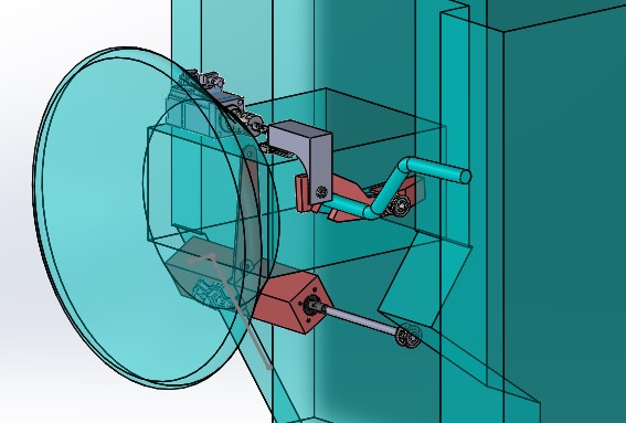
The final design I came up with is pictured below. Ultimately, I decided it was most feasible to use two different actuators instead of one. Motor 1 is responsible for actuating the primary rotational motion to toggle between gears. Motor 1 is housed in a carriage that runs below the steering wheel. This housing carriage needed to be strong enough to accommodate the weight and torque of both Motor 1 and the reducer appended to Motor 1. This carriage is attached to the steering at points with pre-existing bolts. The carriage is also fastened to the Motor-Reducer pair at the front of the Reducer in order to handle the torque produced. This carriage design comes in two parts that are comparable to two half eggshells that come together to close and can be split apart to to open and retrieve the motor.
Motor 1 rotates the shifter bracket via a belt-pulley system. The bottom pulley is simply attached to the shaft of the reducer and the top is attached to a custom designed bracket cap that perfectly fits over the contours of the bracket. This bracket cap was designed after a tedious process of dimensioning the bracket piece using either conventional methods of caliper and ruler or using clay to mold the contours and measuring afterwards.
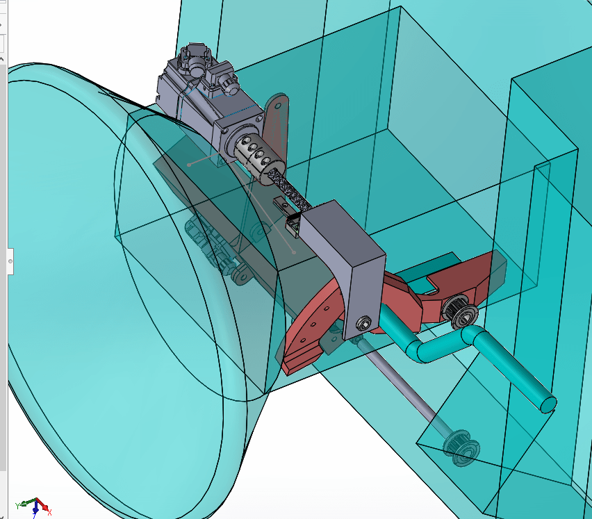
Motor 2 is placed on top of the steering column. Though this is a motor, it is meant to act as a linear actuator used to depress the end of the shift bracket, effectively unlocking the stick. The motor is simply attached to a jig on the top of the steering column and is also attached to this jig at the front of the motor in order to handle to torque of the motor. The shaft of the motor is coupled with a screw which translates the rotational motion to linear motion. A linear car/guiderail system is also used. The guiderail is attached firmly to the top of the steering column and rests directly below and parallel to the screw. The car is attached to a flange that is threaded onto the screw. The car is free to travel along the guiderail as long as the screw rotates and either pushes the car out or pulls it in.
Attached to the flange threaded on the screw is a hook-like mechanism that reaches down to the shift bracket. This hook is not tipped with a sharp spike, but rather with a rolling ball-bearing. The tip of this ball is meant to roll along the end of the bracket cap closer to the driver which has been specifically designed to be a new-and-improved “terrained” piece as mentioned and pictured earlier. This new “terrained” piece is no longer responsible for the stick-unlocking function anymore, as that is performed by linear actuator powered my Motor 2. Instead, all this new “terrained” piece needs to accommodate are 4 different shallow divots that the ball-tipped hook can rest within as a placeholder for the different shift stick positions. Motor 1 simply needs to apply enough torque to get the ball-tipped-hook to roll out of these shallow divots rather than impossibly steep hills.
I personally designed all customized components such as the bracket cap, housing carriage, and ball-tipped hook using SolidWorks and performed FEA on said pieces using SolidWorks FEA and ANSYS. I was even able to manufacture some metal prototypes of the pieces using some personal power tools and materials from Lowes. All other components such as the screws, couplers, and belt-pulley systems were sourced from Mcmaster Carr and Misumi. Finally, servo motors (Motor 1 and Motor 2) as well as reducers were sourced from Anaheim Automation, which was chosen because many of their actuators were compatible with the existing servo drivers facilitating the steering column and pedal actuation.
Looking Back and Moving Forward:
Altogether, I enjoyed my first college internship experience. Given the remote style of the internship, there was, of course, more I wished I could have done or taken away from the experience. Nonetheless, given the circumstances and the nature of my work, I could not have asked for more. Our CEO was very patient and understanding. He walked me through the ins and outs of my designs, allowing me general autonomy over my work yet guiding me where guidance was due. I was even lucky enough to tag along for a couple trips to Richmond Field Station where I could work with the vehicle in-person and spectate for test runs: my first experience being a passenger of an autonomous vehicle.
Even though I would have hoped to be able to manufacture all the components of my design and see it eventually come to life, the chance to design a system for a purpose other than a personal project or school club was a fresh new context to engineering which I took a lot away from. Thank you to Hermes Robotics for fulfilling what would have otherwise been a rather uneventful quarantined summer!